The visual documenting of many good projects is let down by poor lighting and cluttered, messy scenes. When I do photography and video I want to create the best images that I can. To this end I decided to build an infinity cyclorama – or photographic stage. In my case, this means a platform and back wall, with a curved corner between them.
I don’t have much space for storage, so the main requirement was that the finish unit could fold up, or disassemble and be stored flat. I went with folding, as that will give the most manageable result.
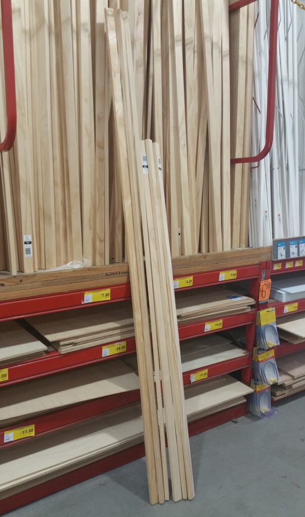 Step 1. Hardware store!
For ease of construction I decided to use timber for the frame. Untreated pine battens (18mm x 36mm) were the obvious choice. They are rigid enough when on edge, light, cheap, and easy to work. Pine is something of a “poor cousin” when it comes to timber. But I use it a lot. It’s great for simple quick work and if you like blond timber, then it looks perfectly fine (in my opinion).
The question of what to make the surface of the stage from was more difficult. Sheet plastic would be ideal, but even finding flat ABS or similar in a large enough sheet size would be a challenge. So I spent some time walking around looking at different materials and eventually found very large sheets (2440mm x 1220mm) of corflute, It was black (rather than the desired white) and the sheets are incredibly easy to create along their length, but it is flat, rigid, yet flexible. Basically, good enough – and with the addition of a roll of white paper on top it would do the job.
I added three small butt hinges and a one meter length of galvanised flat steel bar (for side braces) to my list and headed back to the workshop to assemble it all.
Step 2. Cutting material
I had to guess how much timber I would need for this project (based on the corflute sheet size). So the first job was to estimate the finished depth and height of the stage, by curving the corflute and making some measurements. Then writing up a cutting list. End result:
- 4 lengths x 1200mm – for the platform
- 4 lengths x 900mm – for the back
- 4 lengths x 1000mm – for the ends of the platform and back
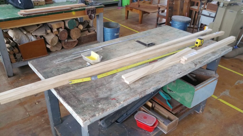 So the stage was 1200mm deep (front to back), 900mm tall, and 1000mm wide.
I marked up the timber, then cut it with a drop saw. I quite like doing this sort of work with a hand saw, but my time was limited today, so the drop saw was the quickest solution.
(BTW – if you are wondering about the taped up tape measure, it’s a long story! Suffice to say it was all I had on hand today as I forgot to bring my toolbox.)
Step 3. Assembly of platform and back
Being a very soft wood pine doesn’t need much care to avoid splitting. However placing screws close to the end of these battens was likely to split the wood, so I marked up the timber and pre-drilled everything just to be sure.
I didn’t have enough screws of any one type, but I collected a few different sorts which would do the job. Given the purely functional nature of the stage I really wasn’t worried with the screws all being one kind. Most of them were button headed, which works well with pine as the large flat head spreads the load and helps prevent splitting which countersunk screws encourage.
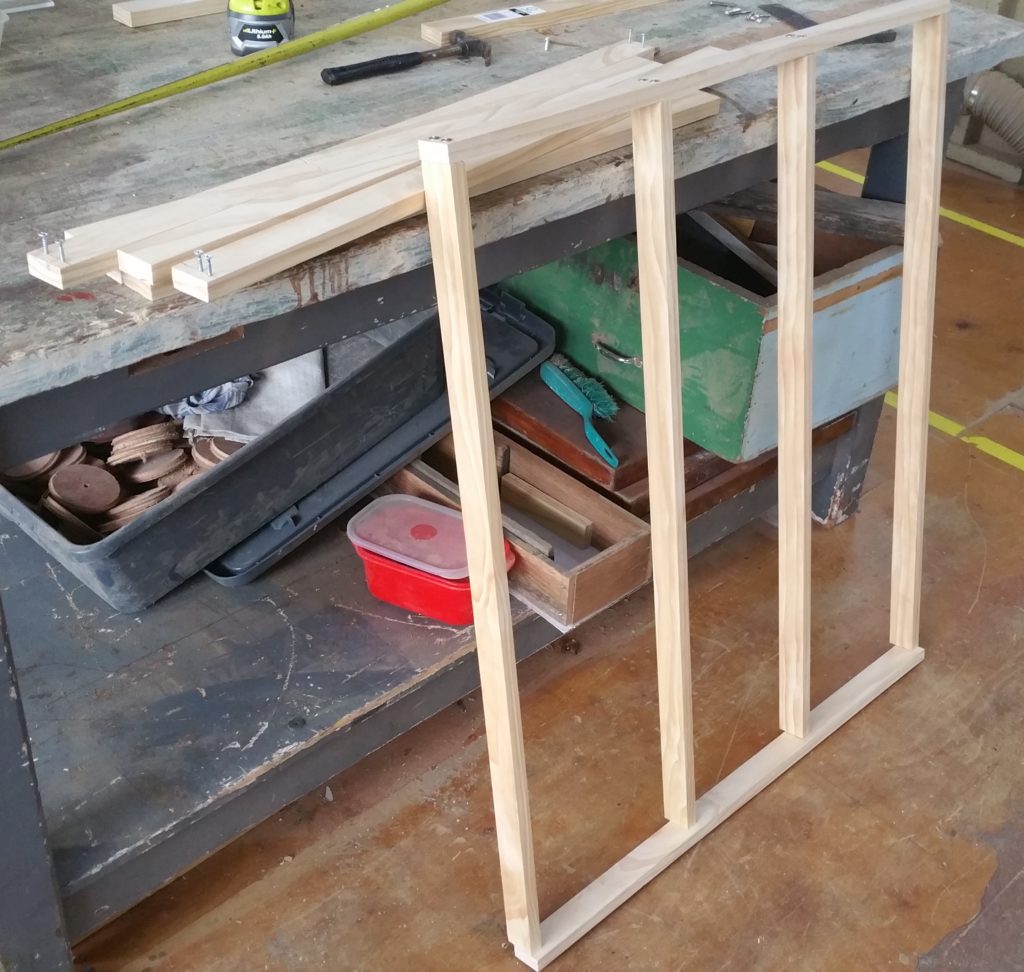 I assembled the platform first with four battens running from front to back to give the corflute plenty of support.
I put two screws into the end of each batten which was plenty to hold them tight. I could have glued the joint as well with PVA or similar, but, like finding matching screws, it really wasn’t necessary.
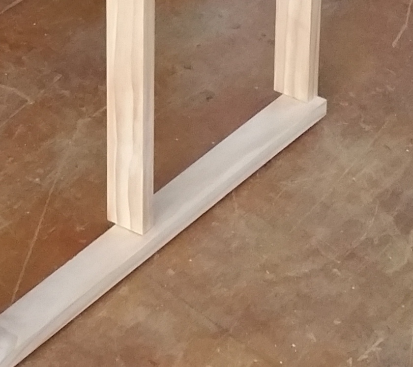 You will note the the cross piece at the front of the platform (closest to the ground) is not aligned with the support battens. This was intentional to create a lip at the front of the platform to hold the corflute.
Here’s a blow-up of the detail…
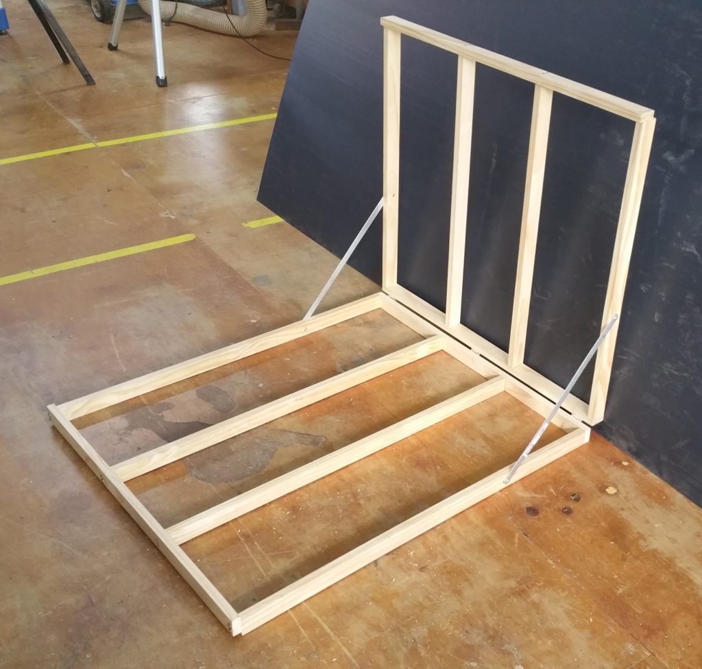
The back panel was assembled in the same way, including stepping the top cross piece forward a little as well to create a second lip to hold the other end of the corflute in.
 Step 4. Structure assembly.
To complete the cyclorama I attached the three hinges to the back of the platform, then to the bottom of the back. They were screwed in with small countersunk screws. The structure was now connected and could be folded up, but there was no way of forcing it to stay at 90 degrees.
To do that I added removable corner braces using the flat steel bar. I cut it in half, into 500mm lengths, ground the points off the ends, drilled a 4mm hole in the ends of each length, then attached them with bolts to the structure. The bolts on the platform side are intended to be permanent, while the bolts that connect the bars to the back are removable to allow the structure to be folded flat for storage.
The resulting structure is very sturdy, and quite rigid while also being able to fold flat.
Step 5.
The last step was to fit and cut the corflute. I forced it into the frame, so that it made the tightest curve possible, then marked where it met the lip on the top of the back, lay the sheet out flat and then cut it.
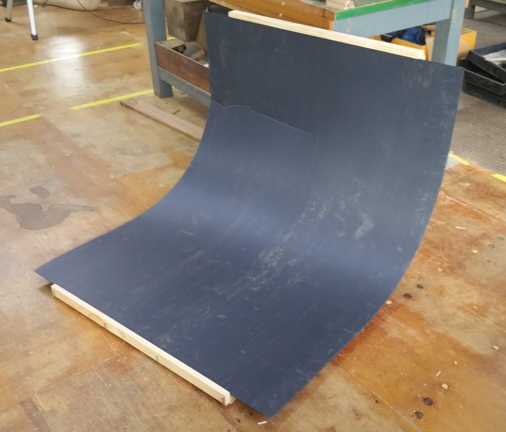 As you can see, the sheet of corflute could then be forced into the frame where it was held by the lip, top and bottom. You can see that this sheet was creased somewhat on one side, that was accidental and happened while being transported. I have bought another sheet so that I can replace it (at $11.85 it wasn’t a disaster).
Conclusion:
Almost total success – which was a pleasant surprise, sine the whole idea was pretty much spur of the moment and not designed out in advance.
I am going to change the angle of the steel bar support braces. Currently they are at 45 degrees, I am going to push that up to about 70 degrees to allow the corflute to stay flat on more of the platform. The bars provide more than enough rigidity as they are, so taking away some of their mechanical advantage will make little or no difference to the frame’s rigidity.
Another modification I could make would be to put a joint in the middle of each bar. This would allow the unit to simply fold down, without the need to remove the bolts from one end. Or I could notch the end of each bar, so that they could simply hook over the bolt. Either way, the pressure from the corflute should hold the frame open when in use.
To be able to use the cyclotron I will need to add a large sheet of paper over the top of the corflute. This was always the intention with this material. Some low tack spray glue (or possibly hair spray) would hold it in place. Using a paper sheet also has the advantage that if I damage it, then I can simply throw it away and put down a new piece.
Overall I am really pleased with the result.


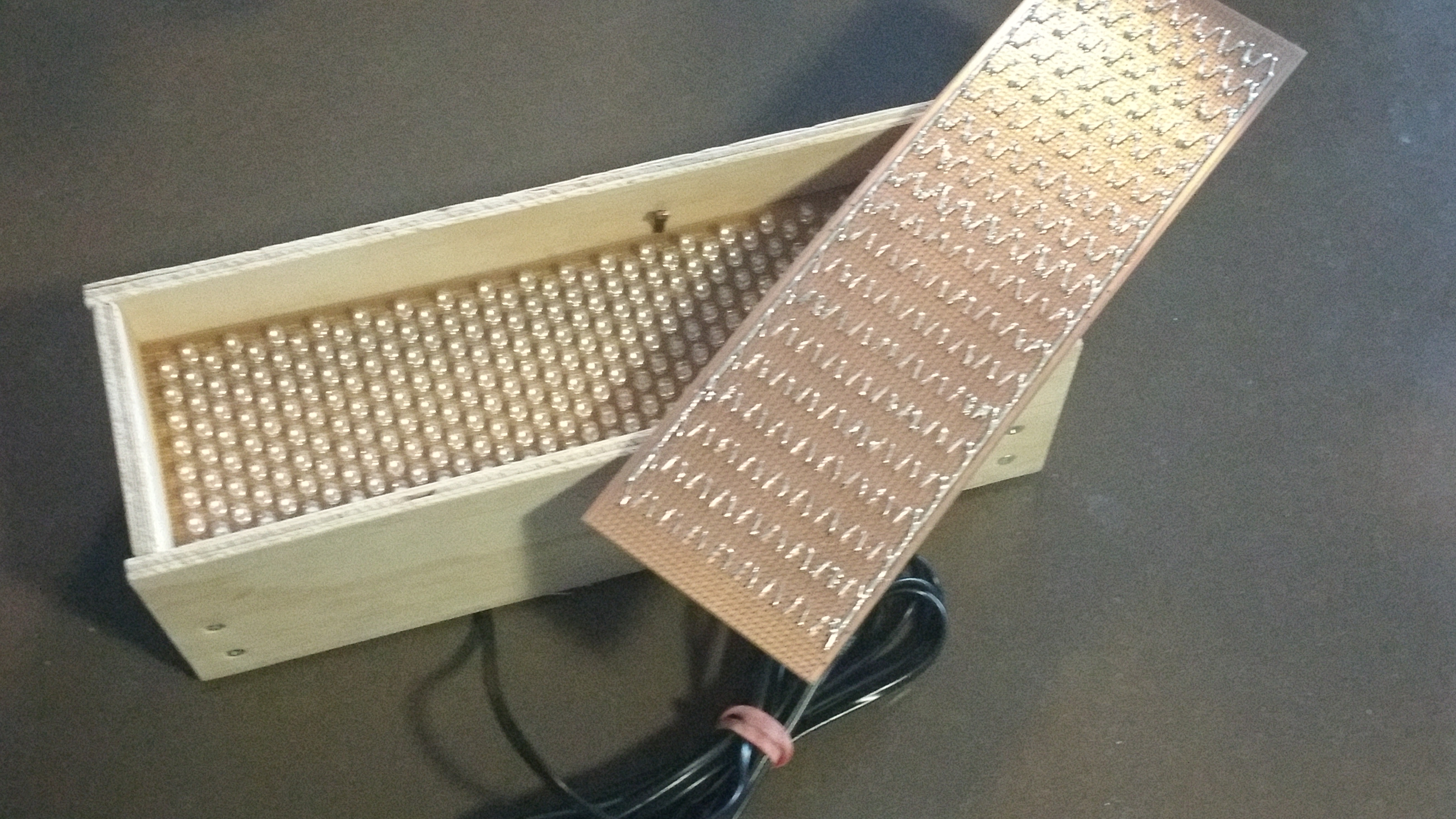
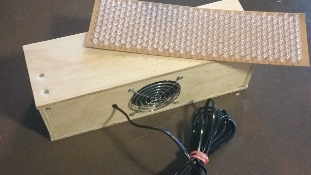 Building the spotlight was an interesting project. It uses 304 infrared LEDs that emit infrared light in the 940 nanometer range. The LEDs have a beam angle of 15 degrees, so the light is reasonably focused without needing a lens on the front of the unit.
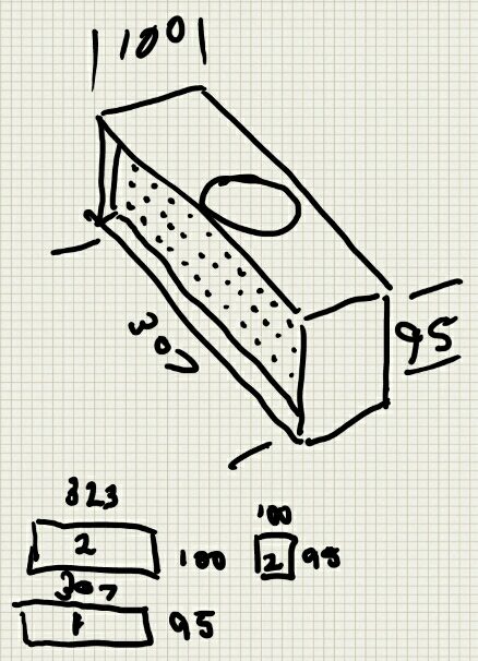 I came across an old sketch that I made of the housing, so I thought I would add it in. I have another set of LEDs mounted and soldered in to another board to make a second unit one day, so it’s good to have the original housing drawing. Note that the cooling fan ended up on the back of the unit rather than the top as suggested here.