Category Archives: Design

Motorcycle helmet HUD – 4

It’s been a while since I did any work on this project, but I pulled out the components the other day and started to look into the Bluetooth connection between the Raspberry Pi and the Feather 32u4 Bluefruit LE board.

It turns out to be complex and on the whole not very well explained how to make these devices talk to each other.  In the final analysis it’s not actually that hard – but you have to do a lot of reading and educate yourself about Bluetooth LE (low energy) before you can actually Make Stuff Happen (TM).

And when you do there are a few limitations that you have to get your head around – like very small data packets.  So no sending long strings for instance.  And then there’s Services and Characteristics and Notification.  Most documenation is far to low level.  Or, if it’s higher level, then it’s vague and poorly explained.

Anyway.  Two days later and I have absorbed – almost – enough Bluetooth LE lore to be able to start to do useful things.  I have achieved connection and data transfer and am working on creating a service that will ultimately allow the Raspberry Pi to send enough data to the Feather board that it will be able to work out how to update the Neopixel strip to correctly reflect current speed.

Progress is happening.

AI is coming to design and engineering

There is one thing in life that you can count on: AI is going to be bigger and happen sooner than almost any of us expect.

Autonomous cars are perhaps the most visible implementations of AI, but it’s creeping in everywhere.  From personal assistants (Sirri, Cortana, Alexa etc), to administration jobs (IBM’s Watson), and now – design and engineering.  Have a look at this article about a team who have applied machine learning to automotive design:

http://www.drive.com.au/motor-news/how-artificial-intelligence-could-design-your-next-car-20170228-gumxy6.html

From the article:

The first Hack Rod prototype created using generative design resulted in a chassis that is 35 per cent lighter than the team’s engineers first managed.

Just let that sink in: on its first try the AI software managed to reduce the weight of a human designed chassis by 35%.

That is unbelievable.  Gains of a few percentage points are what you expect in professional design and manufacturing.  Not 35%.  And this isn’t a design that you can look at and say “Well, ok, now that I have seen it, I could do it too”.  No, this is design that is entirely beyond human ability to ever conceive.

As a deisgner that’s scary – and amazing.

For now we are still in charge of this process.  Controlling and guiding every aspect of it.  However, I can easily imagine a time in the future when an entirely automated, AI guided system can design, build, and operate a fleet of autonomous vehicles, continually monitoring the performance data of the fleet to optimise the physical performance, the satisfaction level of customers to optimise the aesthetics and comfort, and tweaking each new batch of 3D printed cars to improve over the last batch.  No human guidance necessary.

And this isn’t some nebulous, far future, pie-in-the-sky idea.  The pieces are coming together to make this possible very, very quickly.  The McLaren Technology Group already know how to monitor and analyse vehicle performance to the Nth degree.  Market research and analysis of consumer behaviour is what every single company on earth does to some degree or other.  The only missing bit is for AI to tie all of these function together.

The consequences of such a system – economic, social, and political are literally unimaginable at this time.

But the writing is on the wall.  It’s coming.  It’s not going to be stopped.

Magnifier arm

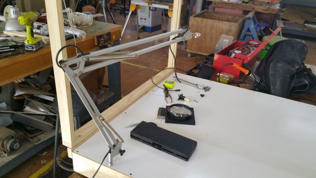
As part of my ongoing upgrade to my photographic stage I decided to add a magnifier on an arm to it.  My eyesight is ok, but when you are dealing with small electronic components it’s sometimes not enough and some artificial help can make all the difference.

I bought a cheap 100mm magnifying glass on a fold up stand.  I also scrounged up an old broken desk lamp (think Luxor Junior).  A little bit of hacking, some stainless steel, and a couple of hand peened rivets later and I had a good result.

The arm has a sleeve on the bottom (that was bent), so after straightening and adding a pin to the side of the photo stage, the whole device can be dropped on, or removed easily.

2016-10-01-15-36-32

I left the power cord for the original lamp in the arm in case it looked like a good idea to add some lighting to the magnifier.  That shouldn’t be necessary with the new lighting on the stage, but it didn’t hurt to leave it for now.

You can also see the small steel rod and plate on the end of the arm that used to hold the lamp shade.  I has a par of holes on the plate that looked ideal to attach the magnifier to.

2016-10-01-16-22-29

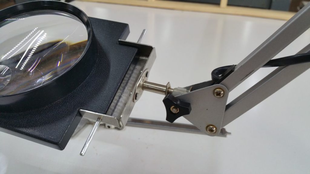
As you can see, the magnifying glass came in a plastic frame.  The original frame had three pieces that allowed it to fold up compact, so I removed the long pin (that you can see in the photo above) and discarded the other two parts of the frame.

Then I found a piece of sheet stainless steel about 1mm thick to make a bracket out of.  I cut the corners out with a hacksaw, then smoothed off the corners and edges with a file.  Finally I folded up three of the sides and drilled holes to allow the rod to slide through and pin the magnifier into the bracket.  It’s all sized to hold the magnifier very tight and secure.  I didn’t want any play in the connection.

Once the bracket was complete, I used the rod and plate from the arm to mark up and then drill two holes in the back of the bracket.  To join the two, I considered using bolts, but decided that a permanent, strong join was the nicest option.  So I made some rivets from 3mm thick steel nails and hand peened them to connect the bracket to the plate.  I am really happy with the result.  It is very strong (stronger than the plate probably!) and looks clean and neat.

2016-10-01-16-22-06

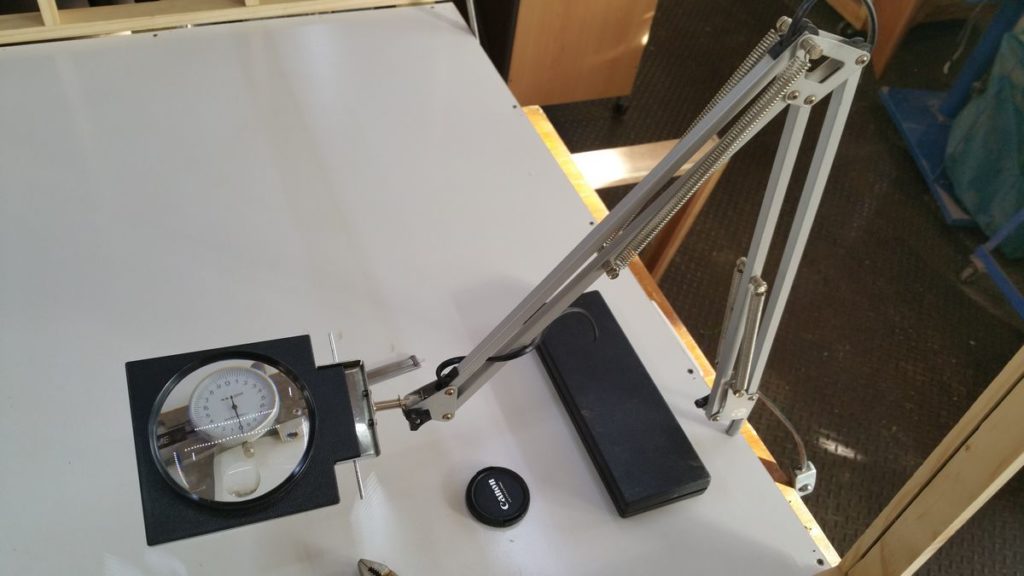
So this is finished arm mounted on the photo stage.  I can easily pull it across when I need to get a better view of what I am working on, but it’s never in the way when not in use, like a free standing magnifier would be.

Total cost: about $10.00 for the magnifier, all the other components were rubbish or scrap that I repurposed.  And it took about three hours to gather the materials and make.  Buying an equivalent device retail would cost me in excess of $100, so I think that this was a worthwhile project.


The Midnight Clock – 2

I have had some further thoughts about the design for the Midnight Clock and wanted to jot them down.

Functionality:

  • Doesn’t turn on at a set time
  • Turns on four hours after its “biphasic” button is pushed
  • Could use two short strips of warm white LED stuck back to back which would allow it to be inserted into an existing lamp like the (decorative) salt lamp that I have
  • Should have a second button that just turns it on and off so that it can also work as an ordinary lamp
  • Should have a dial to adjust brightness in either mode
  • The control box would sit in line between the AC power supply and the LED output
  • The control box could be decorative – I am thinking early twentieth century art deco, phenolic resin radio style
    See: https://www.google.com.au/search?q=art+deco+radio&espv=2&biw=1280&bih=639&source=lnms&tbm=isch

All of this suggests an Arduino controller and I happen to have one kicking around!

Ads, ad blockers and a totally awesome discovery

I include Google ads in this site to generate some income from my project work and the effort of documenting it.  Now, many of you are probably running ad blocking software in your web browsers – I certainly do, so I don’t blame you if you do.

However I learned something important tonight: Google can sometimes serve up some freaking awesome ads!

I am still working on eliminating the personal dating ads (I have managed to kill the awful weight loss ones!), but while testing my site, I discovered that there was an ad for a website called Simscale.

Disclaimer: I have nothing to do with Simscale and have not been paid or induced to endorse them in any way.

I just think that the service that they offer is frickin awesome.

Simscale (https://www.simscale.com/) is a cloud based simulation service that can perform fluid dynamics analysys, finite element analysis (stress analysis), and thermodynamic analysis of your project.  You upload your 3D model, configure the simulation (non-trivial, but doable), and their cloud system computes the results for you.  You can pay for the computer time to keep it private, or make it a public project and they will do the computation for free!  That is a seriously good deal.

Designing a piece of machinery, or a tool and want to know if the design is robust enough?  Simscale can tell you where the points of failure will likely be.  Want to simulate the airflow in a building (or through a heat recovery system) – Simscale can tell you what will happen.

When I studied industrial design over twenty years ago, this sort of analysis was vastly expensive and mentioned only in passing by our lecturers.  Now days, it’s completely commoditised and accessible to just about anyone with and internet connection, 3D modeling software, the inclination to learn some new skills, and a few hours.

Any way you look at it, this is an amazing service – and one that I am seriously contemplating using with my projects.

The Midnight Clock – 1

I love sleep. I really love a good long sleep and waking feeling well rested. It’s not the easiest thing to do though these days. Our lives are so busy, there are so many demands and temptations to stay up late and get up early. As the Bon Jovi song goes: “Until I’m six feet under / Baby I don’t need a bed / Gonna live while I’m alive / I’ll sleep when I’m dead…”

I love staying up late, and often find that I am very productive between midnight and 2.00am. However, since I almost inevitably wake up around 7.00am this limits my sleep to only five hours a night. Not enough for me. I really like seven to eight hours.

All in all it makes it difficult to get enough sleep and most importantly quality sleep. So when I recently saw this TED talk by Jessa Gamble about “biphasic sleep”, I was immediately captivated by the idea. Jessa’s research suggested that human beings evolved not to sleep the whole night through, but to sleep in two portions. One early in the night, the other a couple of hours later. The gap being filled by low level activity like talk, sex, reading etc.

You can read a longer article about Jessa’s work here:

http://magazine.utoronto.ca/feature/jessa-gamble-circadian-rhythm-chronobiology-seasonal-affective-disorder-polyphasic-sleep/

This style of sleep appeals to me strongly I am often tired in the early evening and ready for a sleep, but I force myself to stay up until later so that I will sleep right through and (hopefull
y) not wake up. But it’s a Catch22, since when I get to 11.00pm or midnight, I start to wake up again and feel active. That leads to me sometimes staying up too late researching an idea, or doing something else and then not getting enough sleep.

Biphasic sleep seems like the ideal answer – sleep for a while early in the evening when I am tired from a hard days work, wake up for a couple of hours and enjoy that uniquely quiet and peaceful time in the middle of the night, then drift off back to sleep again and sleep until dawn. It seems to suit my circadian rhythm really well.

So I decided to try it out. I have had two nights of early to bed with short periods of being awake in the middle of the night (which surprisingly) just happened naturally – I woke up around midnight without and prompts, and then drifted off to sleep again around 2.00am.

The only problem was that when I woke up, I had no idea what time it was and I found turning over and looking at the clock disturbing. I really didn’t want to do it. This lead me to thinking about a new project – something that I have dubbed The Midnight Clock.

The Midnight Clock would (as the name suggests) turn on around midnight. I would not however be harsh and bright, it would be a soft light that would gradually increase in brightness (to perhaps the intensity of a 10 watt incandescent globe) over the course of about 20 minutes, then hold that brightness until about an hour and ten minutes, at which point it would slowly fade away over the course of half an hour to nothing.

If I was very tired and just wanted to sleep, this “clock” would not wake me up, nor would it keep me awake. But it would be a direct indication of the time if I happened to wake up and wonder. If it’s fully dark, that’s ok, go back to sleep. If it’s getting lighter, then it’s ok to wake up more…

I am thinking that LEDs (warm white, or RGB which I could tune to an orange/red part of the spectrum) would be ideal, driven by an Arduino board to handle the light level and timing. The Adruino would be capable of driving the LEDS without needing a separate power supply and pulse width modulation (PWM) hat or add on, so the system would be simple and compact.

I am going to put this project on my list for the near future. It’s a good little one day Quick Project and would be a nice addition to my on going science experiment with sleep.


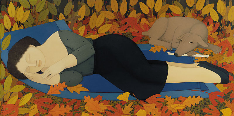
The image attached to this post is an oil painting by Andrew Stevovich, Woman with Autumn Leaves, 1994, 36″ x 72″, Private Collection
from: https://commons.wikimedia.org/wiki/File:Andrew_Stevovich_oil_painting,_Woman_with_Autumn_Leaves,_1994,_36%22_x_72%22.jpg

Motorcycle helmet HUD – 3

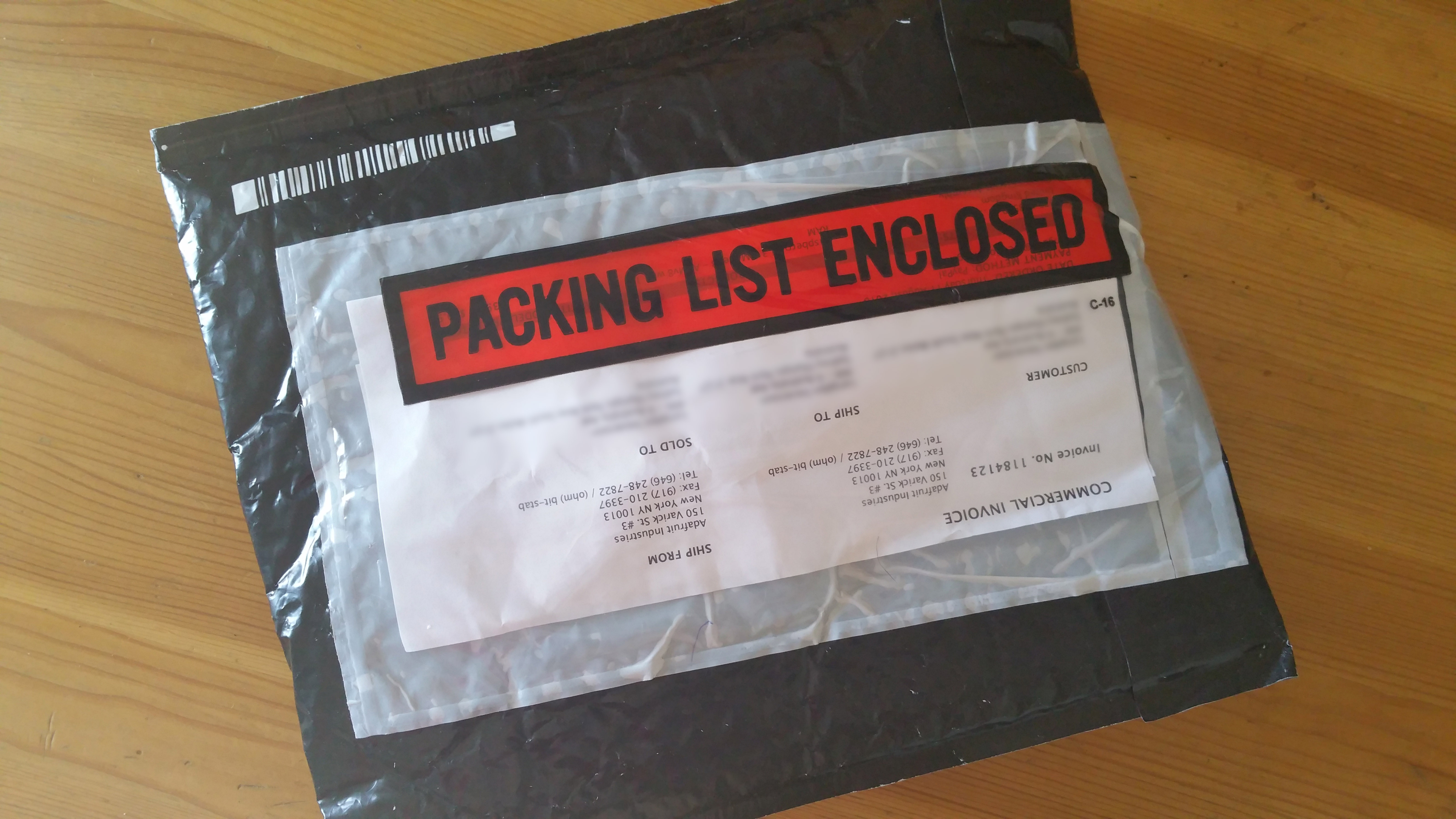
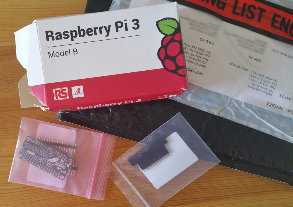
2016-08-23 08.26.00I may still be waiting for my 3D printer to arrive, but in the mean time, the components for my HUD were waiting in the mail box today!

It included a Rasberry Pi model 3 B, an Adafruit Feather Bluefruit (bluetooth enabled Feather development board) and some headers for the Bluefruit.

So now I’m ready to push forward with this project and get the electronics finalised.  Once the 3D printer arrives, then I can start working on housings for the electronics.  Lots to plan and lots to do!


Motorcycle land speed record attempt

There is something about Englishmen and going REALLY fast.  They seem to be very good at it.  Both the engineering involved in building land speed record cars and driving them.

The current land speed record is held by Andy Green, driving the ThrustSSC (that’s: SuperSonic Car) and yes, ThrustSSC did break the sound barrier on land on four wheels with an average speed over one mile in two passes of 1227.986 km/h.  Any way you look at it, that’s insanely fast.

Not content with that, Richard Noble, who lead the ThrustSCC team, is now aiming for 1000 mph (1600 km/h) with his next project Bloodhound SSC.

But now Triumph, with the help of Isle of Man legend Guy Martin, are aiming to push the motorcycle land speed record from 376.363 mph to 400 mph with the Triumph Infor Rocket.  So once again English engineering and pilot are pushing the boundaries of what’s possible.

I read the Triumph Infor Rocket in Wired Magazine online.  You can see the article here.

Specs for this insane motorcycle:

  • 25.5 feet long
  • Two 1.4 liter engines
  • 1000 horsepower
  • Parachute for braking

That is one very, very serious bike – and it’s a Triumph!  I have a special soft spot for this land speed record attempt, as I ride a Triumph myself – a 2004 Daytona 955i.  It would be great to see Triumph take back a title that they haven’t held since the Triumph powered Gyronaut X-1 set a land speed record of 395.363 km/h in 1966 – that’s 50 years ago.

Here’s hoping that the Rocket and Guy Martin can do it.

Motorcycle helmet HUD – 2

Ok, today has been an interesting day for discoveries.  I was thinking about the limitations of having to have a wired connection between the helmet and main unit on the bike and it got me thinking about Bluetooth and wireless options.

The first thing I discovered (which I wasn’t aware of) is that basic Bluetooth modules (and slave and master pair) can be readily inserted in place of a serial connection between devices.  Unfortunately I don’t think that this would work in the case of driving the Neopixel LED strip that I am planning on using for speed display, but it did point me in the right direction.

What I found was the Adafruit Feather 32u4 Bluefruit LE Arduino development board:

https://www.adafruit.com/products/2829

It’s a fully functional Arduino single board computer with the following features:

  • Size: 51mm x 23mm x 8mm
  • USB powered
  • Built in lithium ion polymer battery charger (!)
  • Bluetooth 4.0 Low Energy module
  • Heaps of GPIO pins

And it’s cheap (USD$30).  All of this makes it perfect for controlling the LED strip.  It’s small, batter powered, low power consumption, has Bluetooth for communication, and is perfect for controlling LEDs.

I have ordered one to play with and get a feel for Arduino (which I haven’t used before).  So my Raspberry Pi 3 B (which also has Bluetooth 4.0 support) should be able to talk directly to the Feather and issue commands about what light pattern to display.

This means that the helmet components just got more complex, but it should be worth the hassle to have a wire free connection.

Invisible IR spotlight

Another old project that I recently dug up and want to complete is this REALLY powerful invisible infrared spotlight.

I chose 940 nanometer infrared LEDs for the job as they are completely invisible to the naked eye.  I should insert a WARNING here:

If you are thinking of replicating this project, you need to be aware that it is uncertain if very powerful IR light like this can damage the retina in the eyes of humans and animals.  Therefore, the best thing to do is to be cautious.  DON’T look into the IR beam directly.

DON’T point the beam at people or animals that are close.  No-one wants eye damage.  Safety first, last, always.

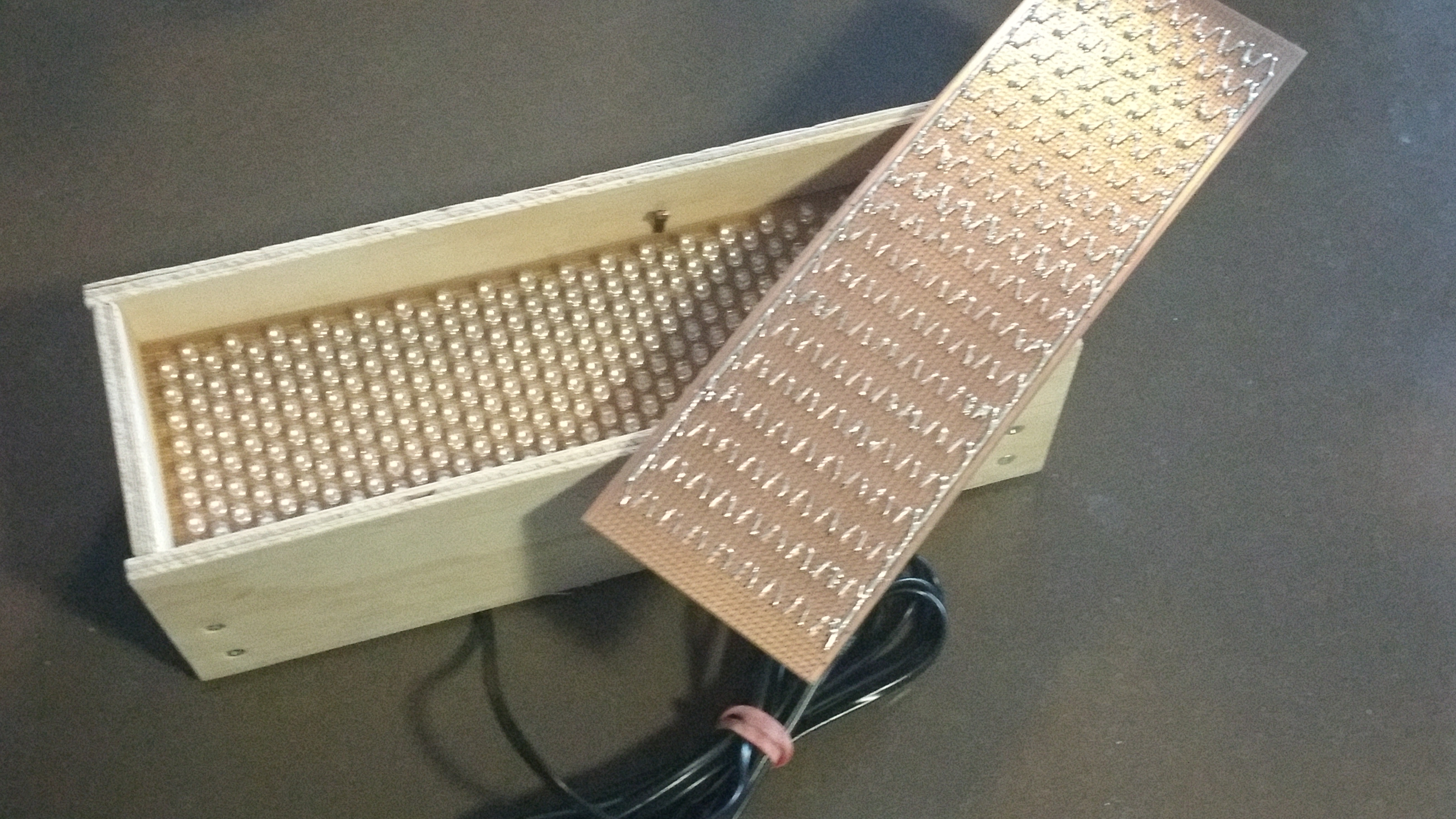
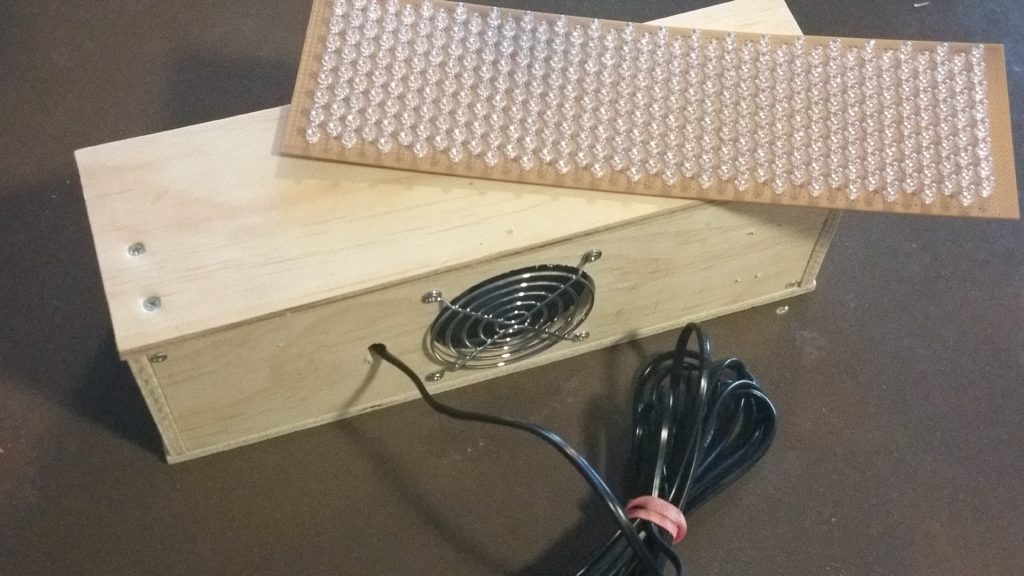
2016-08-07 17.02.59Building the spotlight was an interesting project.  It uses 304 infrared LEDs that emit infrared light in the 940 nanometer range.  The LEDs have a beam angle of 15 degrees, so the light is reasonably focused without needing a lens on the front of the unit.
It has a light sensor in it, so that it automatically turns on in low light conditions where a wildlife cam, or CCTV camera might need extra illumination.

I also added a fan to the enclosure as the density of the LEDs lead to a fair amount of heat being generated!

The power supply to the unit is 24 volts to keep the current draw down, so there is a 24 to 12 volt transformer in the housing as well to run the cooling fan.

Testing of the prototype went well, the LEDs are seriously bright and made for very effective illumination in total darkness.

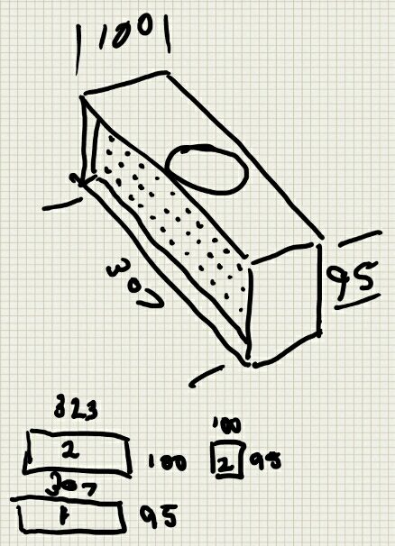
ir-spotlight-casingI came across an old sketch that I made of the housing, so I thought I would add it in.  I have another set of  LEDs mounted and soldered in to another board to make a second unit one day, so it’s good to have the original housing drawing.  Note that the cooling fan ended up on the back of the unit rather than the top as suggested here.

I will post more about this project in due course.