All posts by Langdon

Motorcycle helmet HUD – 4

It’s been a while since I did any work on this project, but I pulled out the components the other day and started to look into the Bluetooth connection between the Raspberry Pi and the Feather 32u4 Bluefruit LE board.

It turns out to be complex and on the whole not very well explained how to make these devices talk to each other.  In the final analysis it’s not actually that hard – but you have to do a lot of reading and educate yourself about Bluetooth LE (low energy) before you can actually Make Stuff Happen (TM).

And when you do there are a few limitations that you have to get your head around – like very small data packets.  So no sending long strings for instance.  And then there’s Services and Characteristics and Notification.  Most documenation is far to low level.  Or, if it’s higher level, then it’s vague and poorly explained.

Anyway.  Two days later and I have absorbed – almost – enough Bluetooth LE lore to be able to start to do useful things.  I have achieved connection and data transfer and am working on creating a service that will ultimately allow the Raspberry Pi to send enough data to the Feather board that it will be able to work out how to update the Neopixel strip to correctly reflect current speed.

Progress is happening.

A local supplier of Adafruit components in Australia

If you are thinking of buying Adafruit components like the ones I regularly use in my projects and you don’t want to pay for, or wait for shipping from the US then you are in luck!

I recently discovered that you can order Adafruit components from Core Electronics in Australia.  They claim to stock the entire range of Adafruit components.

You can find them here:

https://core-electronics.com.au/

AI is coming to design and engineering

There is one thing in life that you can count on: AI is going to be bigger and happen sooner than almost any of us expect.

Autonomous cars are perhaps the most visible implementations of AI, but it’s creeping in everywhere.  From personal assistants (Sirri, Cortana, Alexa etc), to administration jobs (IBM’s Watson), and now – design and engineering.  Have a look at this article about a team who have applied machine learning to automotive design:

http://www.drive.com.au/motor-news/how-artificial-intelligence-could-design-your-next-car-20170228-gumxy6.html

From the article:

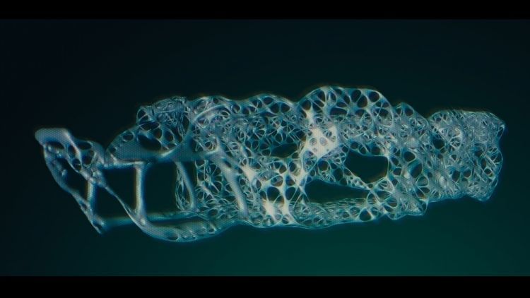
The first Hack Rod prototype created using generative design resulted in a chassis that is 35 per cent lighter than the team’s engineers first managed.

Just let that sink in: on its first try the AI software managed to reduce the weight of a human designed chassis by 35%.

That is unbelievable.  Gains of a few percentage points are what you expect in professional design and manufacturing.  Not 35%.  And this isn’t a design that you can look at and say “Well, ok, now that I have seen it, I could do it too”.  No, this is design that is entirely beyond human ability to ever conceive.

As a deisgner that’s scary – and amazing.

For now we are still in charge of this process.  Controlling and guiding every aspect of it.  However, I can easily imagine a time in the future when an entirely automated, AI guided system can design, build, and operate a fleet of autonomous vehicles, continually monitoring the performance data of the fleet to optimise the physical performance, the satisfaction level of customers to optimise the aesthetics and comfort, and tweaking each new batch of 3D printed cars to improve over the last batch.  No human guidance necessary.

And this isn’t some nebulous, far future, pie-in-the-sky idea.  The pieces are coming together to make this possible very, very quickly.  The McLaren Technology Group already know how to monitor and analyse vehicle performance to the Nth degree.  Market research and analysis of consumer behaviour is what every single company on earth does to some degree or other.  The only missing bit is for AI to tie all of these function together.

The consequences of such a system – economic, social, and political are literally unimaginable at this time.

But the writing is on the wall.  It’s coming.  It’s not going to be stopped.

Sports locker lock fix up

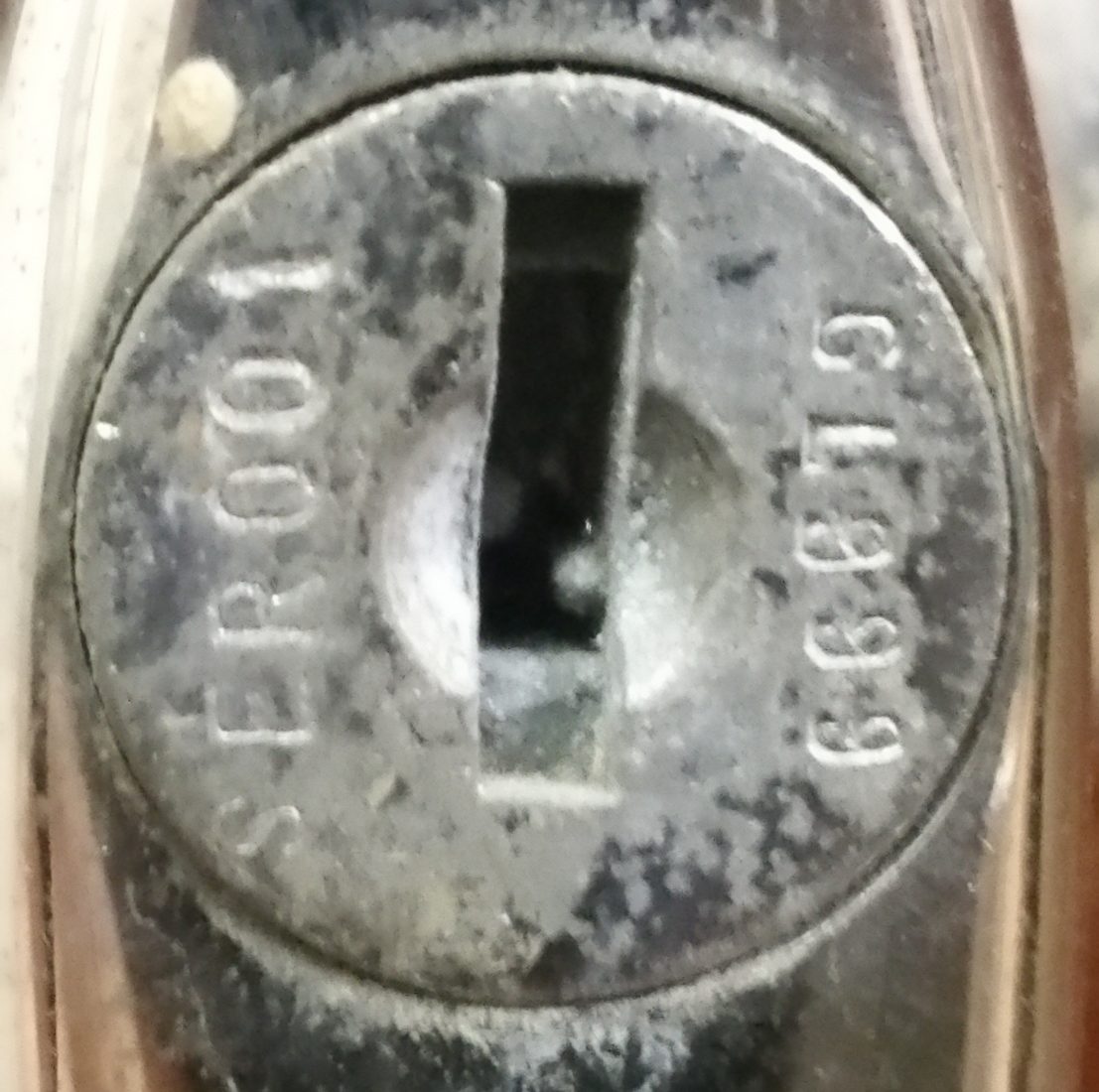
lockI am lucky enough to have a locker at the Men’s Shed that I am a member of.  However, the lockers there are all old and second hand and all missing their keys.  So they aren’t really safe to store valuables in.  I wanted a key for my locker, so I thought I would get one cut.

Initially I just took this photo of the front of the lock to [many] locksmiths and asked them to cut a key.  I have heard that locksmiths have access to vast databases of key codes and all you should have to do is provide a code and they should be able to work out which blank and which pattern to cut on it.

However, none of them could figure it out.  So I decided to pull the whole handle from the locker and see if they could work it out from that.

The following video tells the story – including my foray into lock picking because, why not?

[su_youtube_advanced url=”https://youtu.be/nz9hOvF8piM” responsive=”no” width=”900″ height=”600″  autohide=”yes” rel=”no” theme=”light”]

Magnifier arm

As part of my ongoing upgrade to my photographic stage I decided to add a magnifier on an arm to it.  My eyesight is ok, but when you are dealing with small electronic components it’s sometimes not enough and some artificial help can make all the difference.

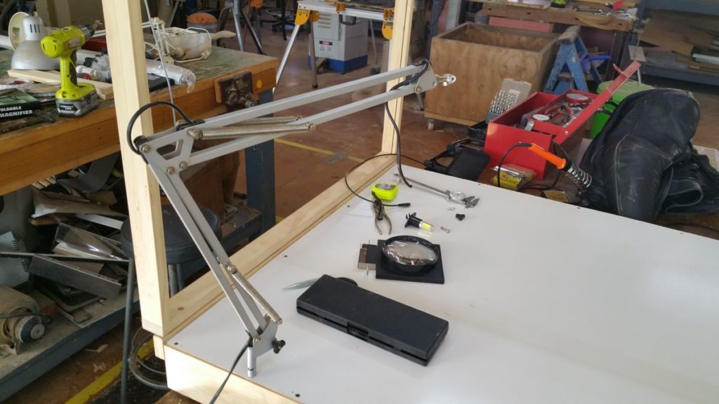
I bought a cheap 100mm magnifying glass on a fold up stand.  I also scrounged up an old broken desk lamp (think Luxor Junior).  A little bit of hacking, some stainless steel, and a couple of hand peened rivets later and I had a good result.

The arm has a sleeve on the bottom (that was bent), so after straightening and adding a pin to the side of the photo stage, the whole device can be dropped on, or removed easily.
2016-10-01-15-36-32

I left the power cord for the original lamp in the arm in case it looked like a good idea to add some lighting to the magnifier.  That shouldn’t be necessary with the new lighting on the stage, but it didn’t hurt to leave it for now.

You can also see the small steel rod and plate on the end of the arm that used to hold the lamp shade.  I has a par of holes on the plate that looked ideal to attach the magnifier to.
2016-10-01-16-22-29

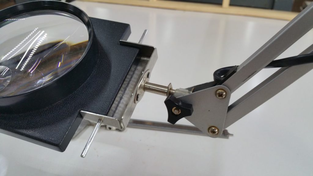
As you can see, the magnifying glass came in a plastic frame.  The original frame had three pieces that allowed it to fold up compact, so I removed the long pin (that you can see in the photo above) and discarded the other two parts of the frame.

Then I found a piece of sheet stainless steel about 1mm thick to make a bracket out of.  I cut the corners out with a hacksaw, then smoothed off the corners and edges with a file.  Finally I folded up three of the sides and drilled holes to allow the rod to slide through and pin the magnifier into the bracket.  It’s all sized to hold the magnifier very tight and secure.  I didn’t want any play in the connection.

Once the bracket was complete, I used the rod and plate from the arm to mark up and then drill two holes in the back of the bracket.  To join the two, I considered using bolts, but decided that a permanent, strong join was the nicest option.  So I made some rivets from 3mm thick steel nails and hand peened them to connect the bracket to the plate.  I am really happy with the result.  It is very strong (stronger than the plate probably!) and looks clean and neat.
2016-10-01-16-22-06

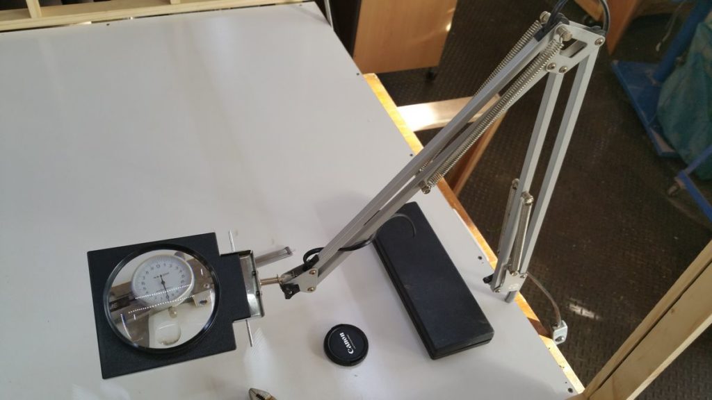
So this is finished arm mounted on the photo stage.  I can easily pull it across when I need to get a better view of what I am working on, but it’s never in the way when not in use, like a free standing magnifier would be.

Total cost: about $10.00 for the magnifier, all the other components were rubbish or scrap that I repurposed.  And it took about three hours to gather the materials and make.  Buying an equivalent device retail would cost me in excess of $100, so I think that this was a worthwhile project.




3D printer has arrived!

After nearly a month long wait my Bee Prusa 3D printer has arrived.

I don’t blame The 3D Shop – who I purchased it from, as their stock was held up by customs.  Just the usual trials of international freight!  They did however keep me appraised of the situation, which was good.

I bought two rolls of filament to go with the printer (since it has two heads) – PLA and PVA.  PLA is mostly good for prototyping, or projects where structural strength of the plastic isn’t important.  PVA filament (yes, it’s the same as the glue!) is great for printing scaffolding.  If your design required support as it is laid down, then PVA is very convenient, once the print process is complete, then the object can be placed in warm water, and the PVA scaffolding simply dissolves away.  It’s very clever and one of the principal reasons that I opted for a twin head printer.

So, the next step is I need to complete my second generation photographic stage (complete with inbuilt LED lighting, mount for camera, power supply for 240V AC, 12V and 5V DC and more.  It’s going to be great and it will let me make a good clear film of the assembly process for the machine.

Learning about potentiometers

As part of The Midnight Clock’s development I am currently learning how to detect the position of a dial using an Arduino.  It’s a relatively simple task – namely, monitor the voltage at the middle leg of a potentiometer using an analog input on the Arduino.

You can see the official Arduino tutorial here: https://www.arduino.cc/en/tutorial/potentiometer

What I discovered was that while the tutorial is correct, the reading from the potentiometer fluctuated (sometimes quite strongly), even when the pot wasn’t being turned.  Now it could be that I have a bad pot that is rather “noisy”, but some googling revealed that this is a common problem with potentiometers.

In my experimentation I am using the detected value from the pot to set the brightness of an LED.  If I simply take the detected value (between 0 and 1023) and use that to set the brightness of the LED (a value between 0 and 254), then it results in a mini “disco” on my breadboard.  The LED flickers higher and lower than the set point.  It’s not good enough for doing real work, especially in a lighting situation where subtlety is required.

There are several solutions to this problem:

  1. Improve the quality of the circuit – this is definitely the first step.  I am currently using a bread-boarded circuit, so it’s likely that I have some connections that are adding noise to the signal
  2. Buy a better quality potentiometer! Accuracy varies between different types of potentiometer I am told
  3. Use a running average of the potentiometer’s output rather than individual readings.  This works, more or less and it is the simplest solution
  4. In addition to calculating a running average, I could attempt to smooth out the signal from the potentiometer by adding a small capacitor to the circuit, from the potentiometer’s middle leg (connected to the analog input pin of the Arduino) to the ground rail
  5. Use an incremental rotary encoder instead of a potentiometer – incremental rotary encoders give a direction and a speed of turn that can be interpreted.  They are what you find in the volume control of modern stereo receivers – you can turn them forever in either direction, and the receiver interprets that as a command to increase or decrease the volume.  This is probably the best solution, but it is quite code heavy and can eat up a lot of an Arduino’s limited memory.  You can read more about them here: http://playground.arduino.cc/Main/RotaryEncoders
  6. Finally, you could use a digital potentiometer and avoid the issue of noisy analog systems all together.  You can see an example here: https://www.arduino.cc/en/Tutorial/DigitalPotentiometer

I will work through these options and report back.

The brief phoenix of driving for Uber

I love – and hate – the idea of self driving cars.  I hate it because I love driving, and I can see a time in the future where I won’t physically be allowed to drive on public roads – or at the very least won’t be able to get the insurance that allows me to self-drive.

I love it because it’s going to make driving so much safer.  The cost to individuals and society of car crashes is huge, financially, physically, and emotionally.

But there is also going to be another cost – that’s to taxi drivers and the people who drive for Uber.  That industry, given a little more time, will simply cease to exist.  It won’t be a gradual decline.  Once the technology is mature, Uber itself will transform from a company that pays people to do ride sharing to a company that provides cars (it may rent your self-driving one from you perhaps), but ultimately the notion of YOU having a car isn’t going to endure.

So everyone who drives a taxi, or for Uber is going to lose their job, because you can bet that the day taxi companies can put a car on the road without a driver, then they will.  In any business the people involved are always the most expensive and troublesome part.  It’s the old IT cliche: “The systems would be perfect if it weren’t for the users”.

Self-driving cars mean no more “users”.  Once you do away with the drivers, the entire eco-system of car ownership and use changes.  Transport as a service is the future.  And the future is officially here:

http://www.skynews.com.au/tech/techinnovation/2016/08/27/self-driving-taxis-released-in-singapore.html

This is the other shoe dropping.  Singapore have done it – they have self-driving taxis.  This will open the flood gates.  Give it a little time for everyone else to see what happens, and if it works without major drama, then governments the world over will be besieged by lobbyists wanting access.

It will be a whole new industry ready to be born, with lots of money to be made.

And all the cabbies out there, what of them?  They will have to hang up their caps and their ID cards and move on to something else.  What?  I have no idea.  Which is sad, because self-driving cars are only the beginning.

Science experiment: biphasic sleep

Intro:

This comes very much in the category of something to “do” rather than make.  But it may well help with the “making” in due course.

If you haven’t read my posts about biphasic sleep, you can see them here and here.  In short, biphasic sleep means sleeping in two blocks, with a period of low activity wakefulness in between.  It is suggested by researcher Jessa Gamble that this is the sleep pattern that humans evolved with and that our brains and bodies can benefit from it.  People who have tried it report having “never felt so awake [during the day]” while following it.

You can see Jessa’s TED Talk about it here.

So I thought that I would try it out and see how it might work for me.  To that end I am going to make a Sleep Diary here on this site and record how I feel after different styles of sleep.  My work interferes with by ability to do biphasic sleep for an extended period, so I will just do what I can.

Aim:

To test if biphasic sleep results in:

  • Better rest
  • Greater day time alertness and acuity

Hypothesis:

I believe that my biology is well suited to biphasic sleep, as I am often drowsy early in the evening, then more awake after midnight, before becoming sleepy again.

Equipment:

I may implement my Midnight Clock in due course.

Procedure:

On any night that I can, I will attempt to go to sleep in a biphasic cycle, starting somewhere around 8.00pm, aiming to wake around midnight, then sleep again from approximately 2.00am.  I will maintain a sleep diary to record my physical response.

Safety/risks:

None known.  If I begin suffering sleep deprivation, then I will stop the experiment

Results:

See Sleep Diary for ongoing results

Discussion/observations:

TBA

Conclusions:

TBA

The Midnight Clock – 2

I have had some further thoughts about the design for the Midnight Clock and wanted to jot them down.

Functionality:

  • Doesn’t turn on at a set time
  • Turns on four hours after its “biphasic” button is pushed
  • Could use two short strips of warm white LED stuck back to back which would allow it to be inserted into an existing lamp like the (decorative) salt lamp that I have
  • Should have a second button that just turns it on and off so that it can also work as an ordinary lamp
  • Should have a dial to adjust brightness in either mode
  • The control box would sit in line between the AC power supply and the LED output
  • The control box could be decorative – I am thinking early twentieth century art deco, phenolic resin radio style
    See: https://www.google.com.au/search?q=art+deco+radio&espv=2&biw=1280&bih=639&source=lnms&tbm=isch

All of this suggests an Arduino controller and I happen to have one kicking around!