Category Archives: Electronics

Motorcycle helmet HUD – 4

It’s been a while since I did any work on this project, but I pulled out the components the other day and started to look into the Bluetooth connection between the Raspberry Pi and the Feather 32u4 Bluefruit LE board.

It turns out to be complex and on the whole not very well explained how to make these devices talk to each other.  In the final analysis it’s not actually that hard – but you have to do a lot of reading and educate yourself about Bluetooth LE (low energy) before you can actually Make Stuff Happen (TM).

And when you do there are a few limitations that you have to get your head around – like very small data packets.  So no sending long strings for instance.  And then there’s Services and Characteristics and Notification.  Most documenation is far to low level.  Or, if it’s higher level, then it’s vague and poorly explained.

Anyway.  Two days later and I have absorbed – almost – enough Bluetooth LE lore to be able to start to do useful things.  I have achieved connection and data transfer and am working on creating a service that will ultimately allow the Raspberry Pi to send enough data to the Feather board that it will be able to work out how to update the Neopixel strip to correctly reflect current speed.

Progress is happening.

A local supplier of Adafruit components in Australia

If you are thinking of buying Adafruit components like the ones I regularly use in my projects and you don’t want to pay for, or wait for shipping from the US then you are in luck!

I recently discovered that you can order Adafruit components from Core Electronics in Australia.  They claim to stock the entire range of Adafruit components.

You can find them here:

https://core-electronics.com.au/

Magnifier arm

As part of my ongoing upgrade to my photographic stage I decided to add a magnifier on an arm to it.  My eyesight is ok, but when you are dealing with small electronic components it’s sometimes not enough and some artificial help can make all the difference.

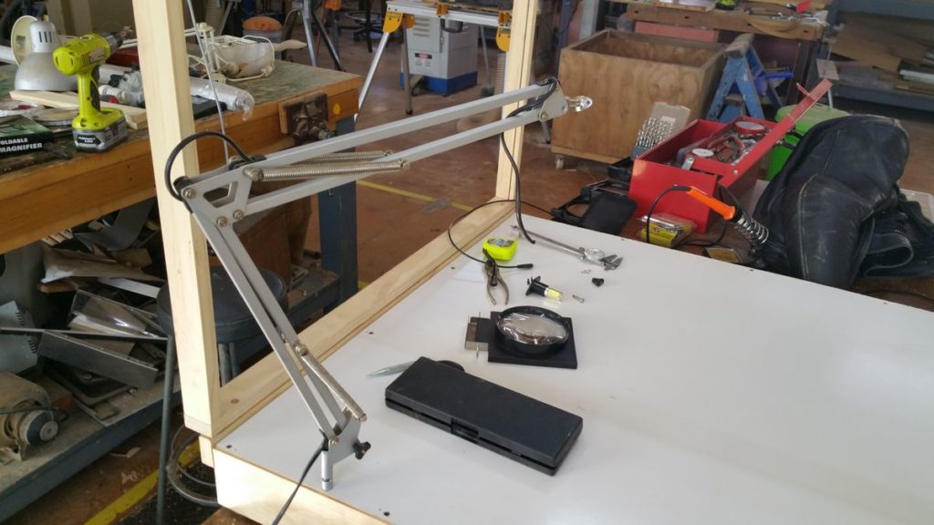
I bought a cheap 100mm magnifying glass on a fold up stand.  I also scrounged up an old broken desk lamp (think Luxor Junior).  A little bit of hacking, some stainless steel, and a couple of hand peened rivets later and I had a good result.

The arm has a sleeve on the bottom (that was bent), so after straightening and adding a pin to the side of the photo stage, the whole device can be dropped on, or removed easily.
2016-10-01-15-36-32

I left the power cord for the original lamp in the arm in case it looked like a good idea to add some lighting to the magnifier.  That shouldn’t be necessary with the new lighting on the stage, but it didn’t hurt to leave it for now.

You can also see the small steel rod and plate on the end of the arm that used to hold the lamp shade.  I has a par of holes on the plate that looked ideal to attach the magnifier to.
2016-10-01-16-22-29

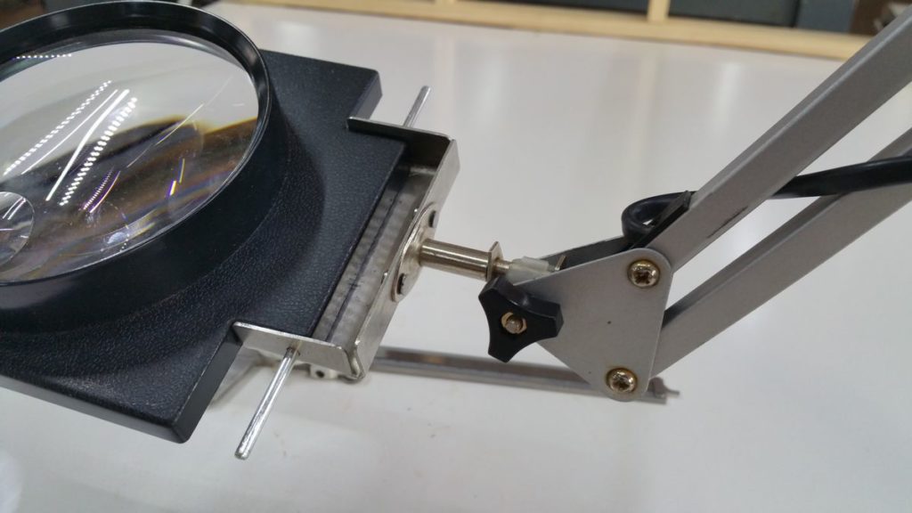
As you can see, the magnifying glass came in a plastic frame.  The original frame had three pieces that allowed it to fold up compact, so I removed the long pin (that you can see in the photo above) and discarded the other two parts of the frame.

Then I found a piece of sheet stainless steel about 1mm thick to make a bracket out of.  I cut the corners out with a hacksaw, then smoothed off the corners and edges with a file.  Finally I folded up three of the sides and drilled holes to allow the rod to slide through and pin the magnifier into the bracket.  It’s all sized to hold the magnifier very tight and secure.  I didn’t want any play in the connection.

Once the bracket was complete, I used the rod and plate from the arm to mark up and then drill two holes in the back of the bracket.  To join the two, I considered using bolts, but decided that a permanent, strong join was the nicest option.  So I made some rivets from 3mm thick steel nails and hand peened them to connect the bracket to the plate.  I am really happy with the result.  It is very strong (stronger than the plate probably!) and looks clean and neat.
2016-10-01-16-22-06

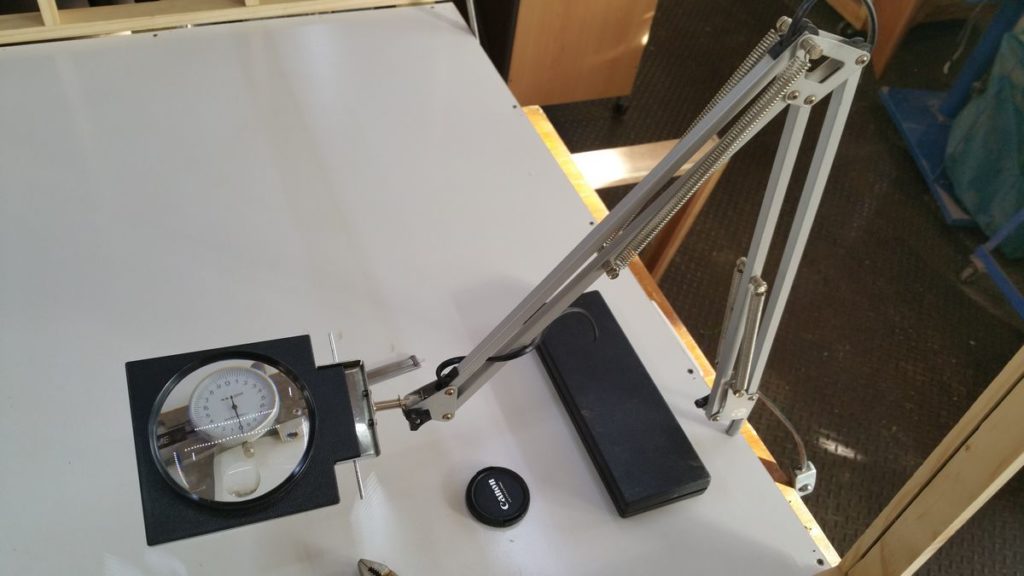
So this is finished arm mounted on the photo stage.  I can easily pull it across when I need to get a better view of what I am working on, but it’s never in the way when not in use, like a free standing magnifier would be.

Total cost: about $10.00 for the magnifier, all the other components were rubbish or scrap that I repurposed.  And it took about three hours to gather the materials and make.  Buying an equivalent device retail would cost me in excess of $100, so I think that this was a worthwhile project.




Learning about potentiometers

As part of The Midnight Clock’s development I am currently learning how to detect the position of a dial using an Arduino.  It’s a relatively simple task – namely, monitor the voltage at the middle leg of a potentiometer using an analog input on the Arduino.

You can see the official Arduino tutorial here: https://www.arduino.cc/en/tutorial/potentiometer

What I discovered was that while the tutorial is correct, the reading from the potentiometer fluctuated (sometimes quite strongly), even when the pot wasn’t being turned.  Now it could be that I have a bad pot that is rather “noisy”, but some googling revealed that this is a common problem with potentiometers.

In my experimentation I am using the detected value from the pot to set the brightness of an LED.  If I simply take the detected value (between 0 and 1023) and use that to set the brightness of the LED (a value between 0 and 254), then it results in a mini “disco” on my breadboard.  The LED flickers higher and lower than the set point.  It’s not good enough for doing real work, especially in a lighting situation where subtlety is required.

There are several solutions to this problem:

  1. Improve the quality of the circuit – this is definitely the first step.  I am currently using a bread-boarded circuit, so it’s likely that I have some connections that are adding noise to the signal
  2. Buy a better quality potentiometer! Accuracy varies between different types of potentiometer I am told
  3. Use a running average of the potentiometer’s output rather than individual readings.  This works, more or less and it is the simplest solution
  4. In addition to calculating a running average, I could attempt to smooth out the signal from the potentiometer by adding a small capacitor to the circuit, from the potentiometer’s middle leg (connected to the analog input pin of the Arduino) to the ground rail
  5. Use an incremental rotary encoder instead of a potentiometer – incremental rotary encoders give a direction and a speed of turn that can be interpreted.  They are what you find in the volume control of modern stereo receivers – you can turn them forever in either direction, and the receiver interprets that as a command to increase or decrease the volume.  This is probably the best solution, but it is quite code heavy and can eat up a lot of an Arduino’s limited memory.  You can read more about them here: http://playground.arduino.cc/Main/RotaryEncoders
  6. Finally, you could use a digital potentiometer and avoid the issue of noisy analog systems all together.  You can see an example here: https://www.arduino.cc/en/Tutorial/DigitalPotentiometer

I will work through these options and report back.

The Midnight Clock – 2

I have had some further thoughts about the design for the Midnight Clock and wanted to jot them down.

Functionality:

  • Doesn’t turn on at a set time
  • Turns on four hours after its “biphasic” button is pushed
  • Could use two short strips of warm white LED stuck back to back which would allow it to be inserted into an existing lamp like the (decorative) salt lamp that I have
  • Should have a second button that just turns it on and off so that it can also work as an ordinary lamp
  • Should have a dial to adjust brightness in either mode
  • The control box would sit in line between the AC power supply and the LED output
  • The control box could be decorative – I am thinking early twentieth century art deco, phenolic resin radio style
    See: https://www.google.com.au/search?q=art+deco+radio&espv=2&biw=1280&bih=639&source=lnms&tbm=isch

All of this suggests an Arduino controller and I happen to have one kicking around!

Motorcycle helmet HUD – 3

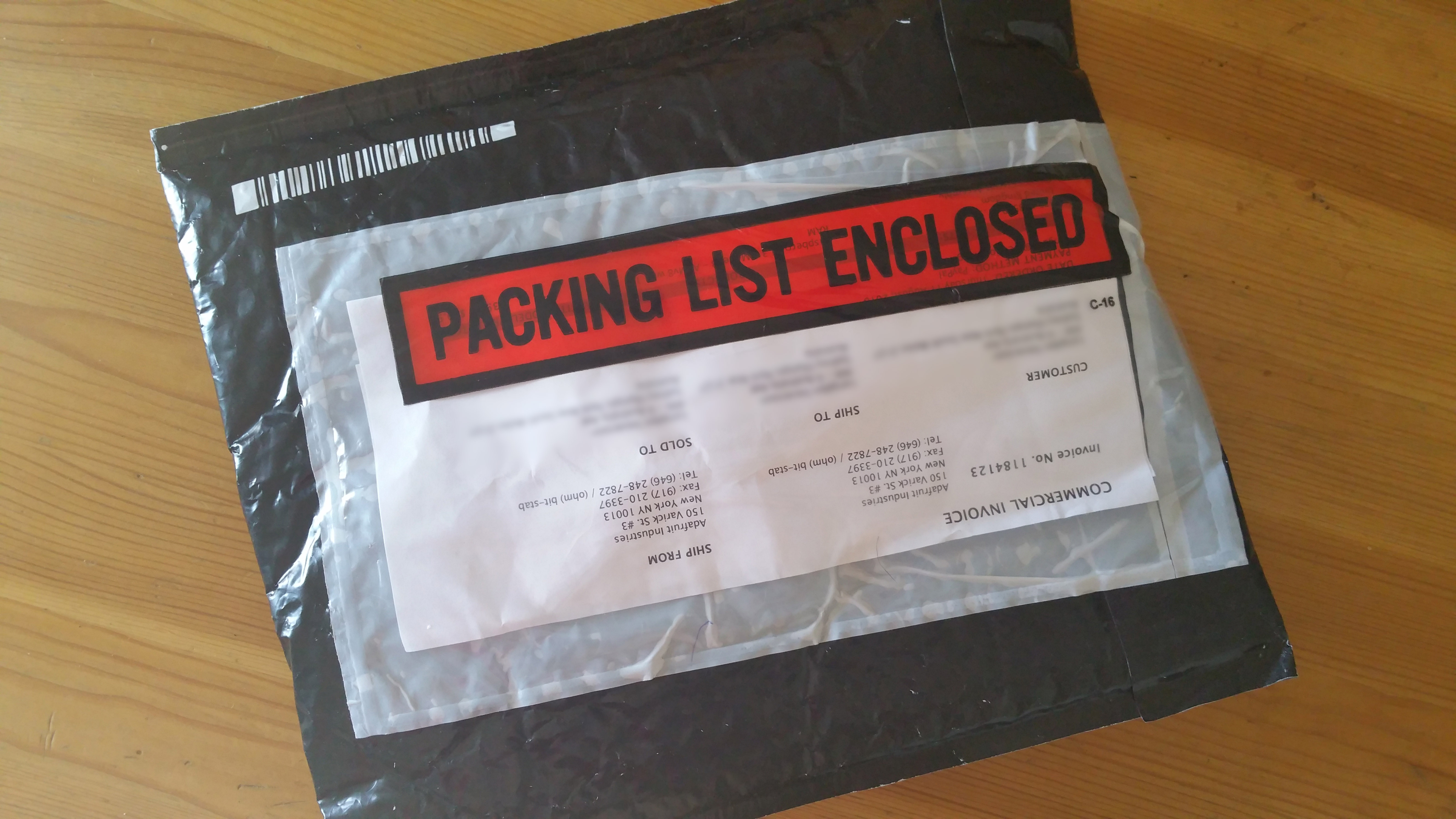
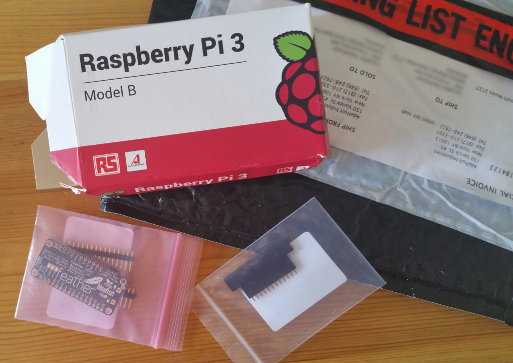
2016-08-23 08.26.00I may still be waiting for my 3D printer to arrive, but in the mean time, the components for my HUD were waiting in the mail box today!
It included a Rasberry Pi model 3 B, an Adafruit Feather Bluefruit (bluetooth enabled Feather development board) and some headers for the Bluefruit.

So now I’m ready to push forward with this project and get the electronics finalised.  Once the 3D printer arrives, then I can start working on housings for the electronics.  Lots to plan and lots to do!


Fuel level sender unit examination

The fuel light on my motorcycle (a Triumph Dayton 955i) came on recently and steadfastly refused to go off, even with a full tank of fuel.

My mechanic swapped it out for a new unit and gave me the old one to play with.  I have often wondered exactly how a fuel sender unit works, so I took it apart and investigated.

[su_youtube_advanced url=”https://youtu.be/3n56y_591iI” responsive=”no” width=”900″ height=”600″  autohide=”yes” rel=”no” theme=”light”]

Motorcycle helmet HUD – 2

Ok, today has been an interesting day for discoveries.  I was thinking about the limitations of having to have a wired connection between the helmet and main unit on the bike and it got me thinking about Bluetooth and wireless options.

The first thing I discovered (which I wasn’t aware of) is that basic Bluetooth modules (and slave and master pair) can be readily inserted in place of a serial connection between devices.  Unfortunately I don’t think that this would work in the case of driving the Neopixel LED strip that I am planning on using for speed display, but it did point me in the right direction.

What I found was the Adafruit Feather 32u4 Bluefruit LE Arduino development board:

https://www.adafruit.com/products/2829

It’s a fully functional Arduino single board computer with the following features:

  • Size: 51mm x 23mm x 8mm
  • USB powered
  • Built in lithium ion polymer battery charger (!)
  • Bluetooth 4.0 Low Energy module
  • Heaps of GPIO pins

And it’s cheap (USD$30).  All of this makes it perfect for controlling the LED strip.  It’s small, batter powered, low power consumption, has Bluetooth for communication, and is perfect for controlling LEDs.

I have ordered one to play with and get a feel for Arduino (which I haven’t used before).  So my Raspberry Pi 3 B (which also has Bluetooth 4.0 support) should be able to talk directly to the Feather and issue commands about what light pattern to display.

This means that the helmet components just got more complex, but it should be worth the hassle to have a wire free connection.

Invisible IR spotlight

Another old project that I recently dug up and want to complete is this REALLY powerful invisible infrared spotlight.

I chose 940 nanometer infrared LEDs for the job as they are completely invisible to the naked eye.  I should insert a WARNING here:

If you are thinking of replicating this project, you need to be aware that it is uncertain if very powerful IR light like this can damage the retina in the eyes of humans and animals.  Therefore, the best thing to do is to be cautious.  DON’T look into the IR beam directly.

DON’T point the beam at people or animals that are close.  No-one wants eye damage.  Safety first, last, always.

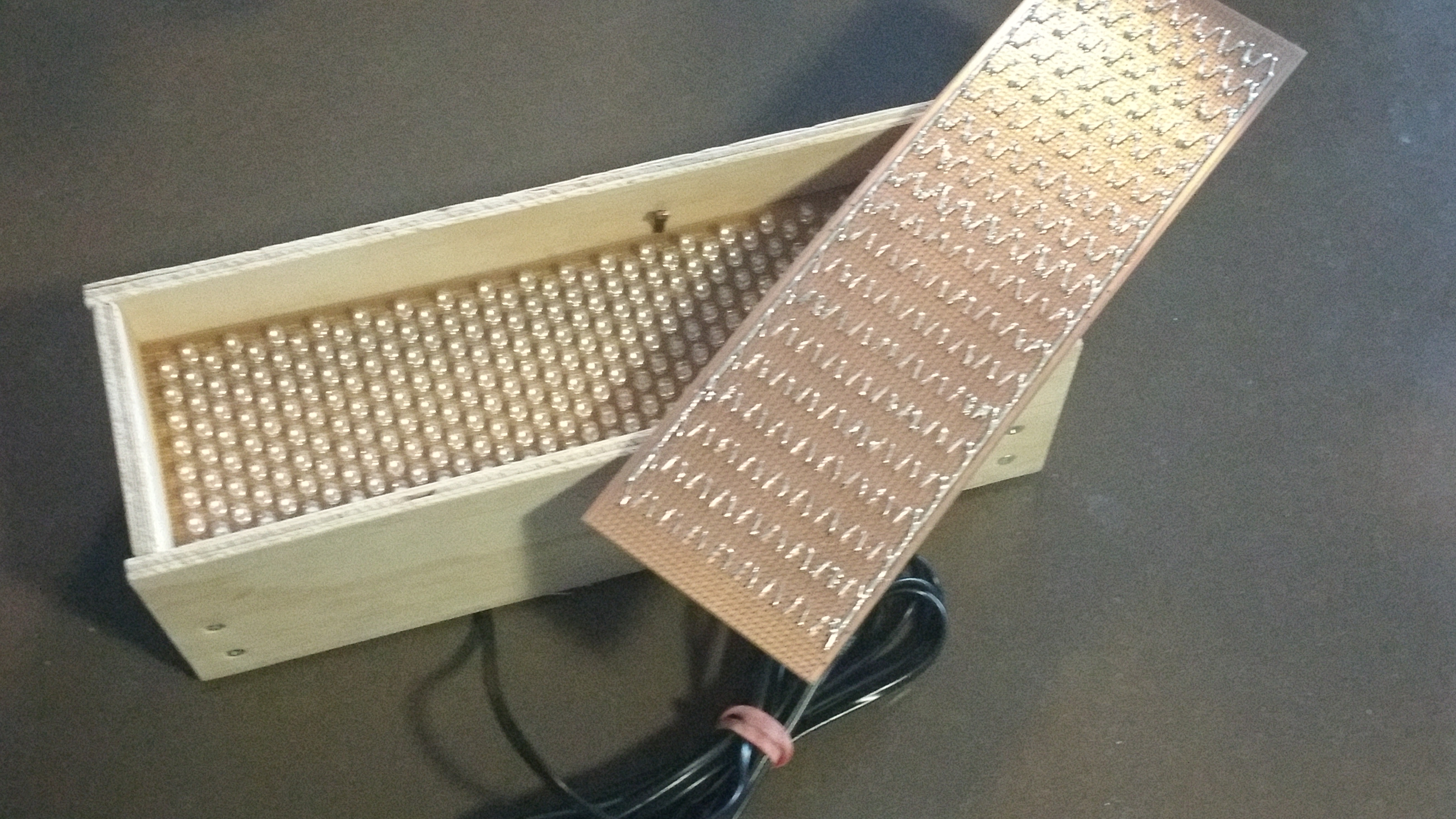
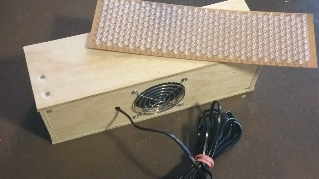
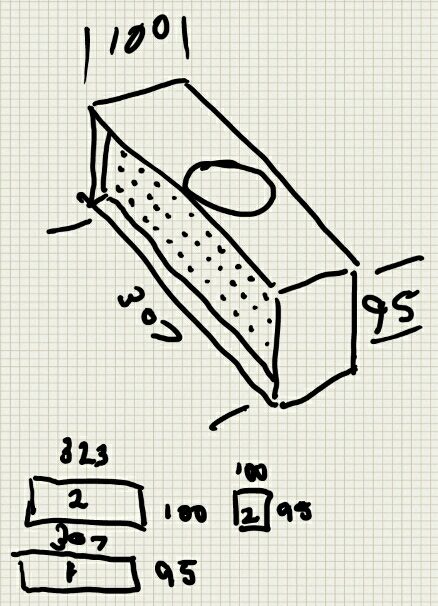
2016-08-07 17.02.59Building the spotlight was an interesting project.  It uses 304 infrared LEDs that emit infrared light in the 940 nanometer range.  The LEDs have a beam angle of 15 degrees, so the light is reasonably focused without needing a lens on the front of the unit.
It has a light sensor in it, so that it automatically turns on in low light conditions where a wildlife cam, or CCTV camera might need extra illumination.

I also added a fan to the enclosure as the density of the LEDs lead to a fair amount of heat being generated!

The power supply to the unit is 24 volts to keep the current draw down, so there is a 24 to 12 volt transformer in the housing as well to run the cooling fan.

Testing of the prototype went well, the LEDs are seriously bright and made for very effective illumination in total darkness.

ir-spotlight-casingI came across an old sketch that I made of the housing, so I thought I would add it in.  I have another set of  LEDs mounted and soldered in to another board to make a second unit one day, so it’s good to have the original housing drawing.  Note that the cooling fan ended up on the back of the unit rather than the top as suggested here.

I will post more about this project in due course.

Motorcycle helmet HUD – 1

This is an old project that I am finally getting back to, with the hope of completing.

I have ridden motorcycles for nearly twenty years, and being tall (6’2″) means that on all of the bikes that I have owned, the instrument cluster is out of my line of site – usually obscured by the chin guard of my helmet (and there is absolutely no way known that I will ever wear an open face helmet).

This is a problem, because it means that I have to frequently take my eyes off the road to check that I am not exceeding the speed limit – something ridiculously easy to do on a modern sports bike.

My solution, which I prototyped over a year ago uses a GPS receiver connected to a Raspberry Pi single board computer, and a stick of RGB LEDs to give a visual indication of speed in the rider’s peripheral vision, where each LED lit corresponds to a speed band (40 to 50kms, 50 to 60kms etc).  The prototype also has an LCD screen and a Raspberry Pi camera that down the track I want to use for automatic speed zone detection (using a convolutional neural network for speed sign identification) but that’s a bigger project for another time.

The prototype worked in stationary testing, but I never got the chance to do testing in a vehicle and the Raspberry Pi has since been scavenged for the Heat Recovery Ventilator project, so I really need to buy another one.

So this is a project that definitely needs to be revived.  I have been off the bike for a while, but did a long trip recently and got thinking about it again seeing all of the police on the road and really missing having cruise control!

Stay tuned.  More to come.